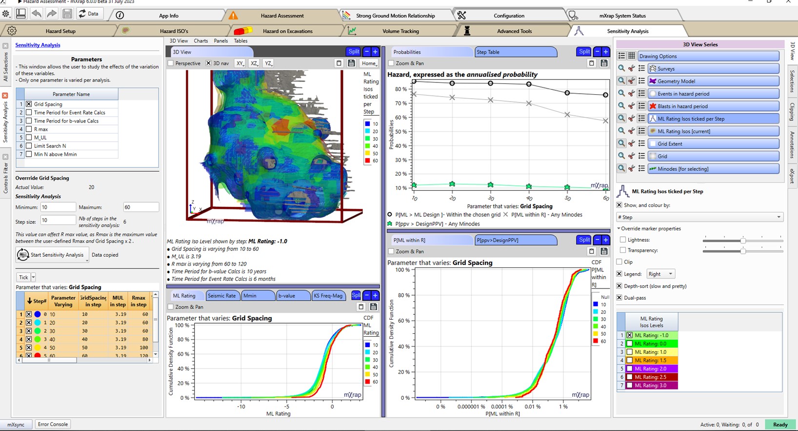
A new window has been added to the Hazard Assessment app (Figure 1). The sensitivity analysis aims to quantify the effect of the variation of the input parameters on the hazard. These analyses can also help the user to determine the optimal settings to use for many of the parameters. This window allows the user to vary only one parameter at the time.
The steps to realize such a sensitivity analysis are quite simple (Figure 2).
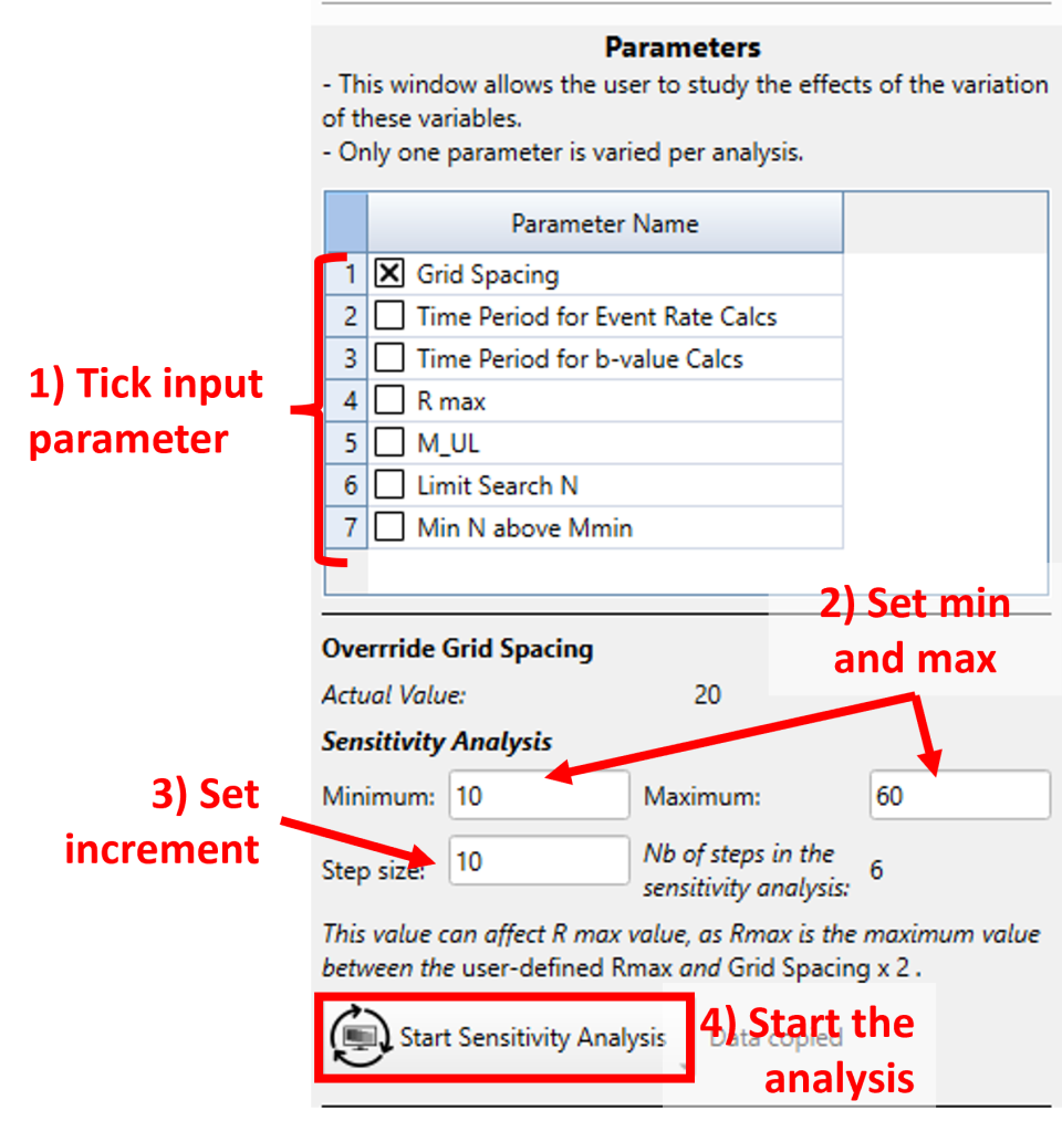
All the input parameters that can be studied are:
- Grid Spacing: Spacing of each grid point defining the grid points in the studied volume (preconfigured grid or override grid extent).
- R max: Maximum search distance (radius) to obtain events for assessing the b-value at a grid point.
- Limit Search N: Search for this many of the nearest events around each grid point. The most important measure to evaluate this parameter is the stability of the b-value fit.
- Min N above Mmin: At least this many events have to be above the local grid Mmin. Choosing a value is a balance between having more stability in the b-value fits and having more grid points using the mine-wide b-value instead of a local one.
- M_UL: Often referred to as MMAX in earthquake seismology, the MUL is a conservative, but realistic estimate of the upper limit of the next largest event the mine could possibly experience. It does not represent the hazard; it is simply a limit that needs to be imposed on the hazard calculation.
- Time Period for Event Rate Calcs: When selecting a time period for event rate calculations, the aim is to find a time period long enough to get a stable result, but short enough to be more representative of the ‘current’ hazard state.
- Time Period for b-value Calcs: The time period used for b-value calculations must be kept long, because a shorter period will mean some areas will not have a hazard. The most important result to consider when evaluating time period for b-value calculations is getting a stable b-value fit, which is quantified by the KS-fit of the Frequency–Magnitude relation.
Examples presented are from the Tasmania root and expressed a sensitivity analysis for the grid spacing.
Annualised probability
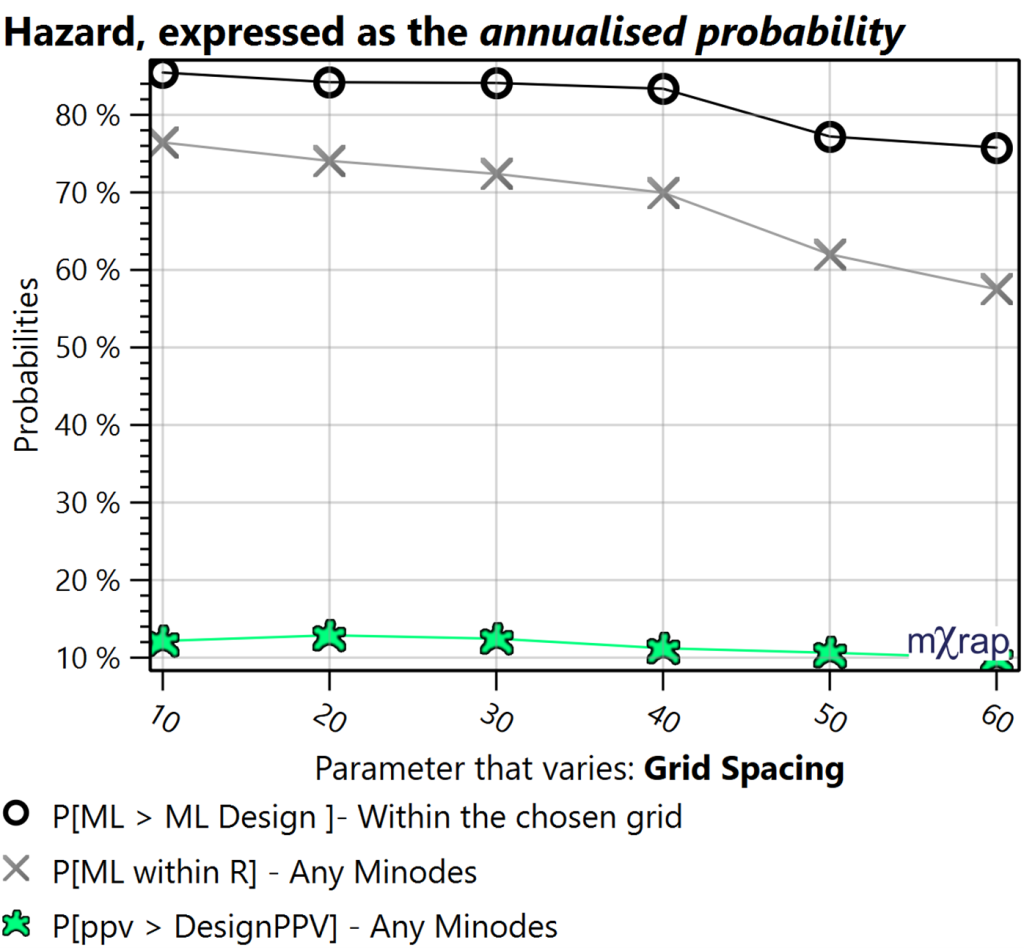
The following hazard calculations all refer to the annualized hazard and apply to the entire volume of the chosen grid:
- P[ML > ML Design]: Annualized hazard for the entire volume of the chosen grid (grid points for the chosen volume) to exceed the design magnitude.
- P [ML within R]: Annualized probability of exceeding the design magnitude within the design distance (R) of the minode location.
- P [PPV > PPVDESIGN]: Annualized probability of exceeding the design PPV, anywhere within the volume associated with the minode (the tunnel section).
The overall variation for the three main hazard assessment are shown in Figure 3.
Grid-based Hazard (Hazard Iso’s window)
The Iso View describes the hazard at all locations within the mine but when you are considering the seismic risk for a particular work area, large events and strong ground motions may come from multiple sources.
Details on hazard Iso’s can be found in the blog post: https://mxrap.com/2018/12/01/what-do-the-hazard-isos-mean/
For the grid-based hazard, the distribution of parameters listed in Table 1 can be investigated. The distribution refers to the value for each grid point composing the volume studied, for which the grid extent and spacing are set.
| Hazard Parameters | Other Parameters |
|---|---|
| ML Rating: Seismic Rate b-value |
Mmin KS Frequency-Magnitude relation |
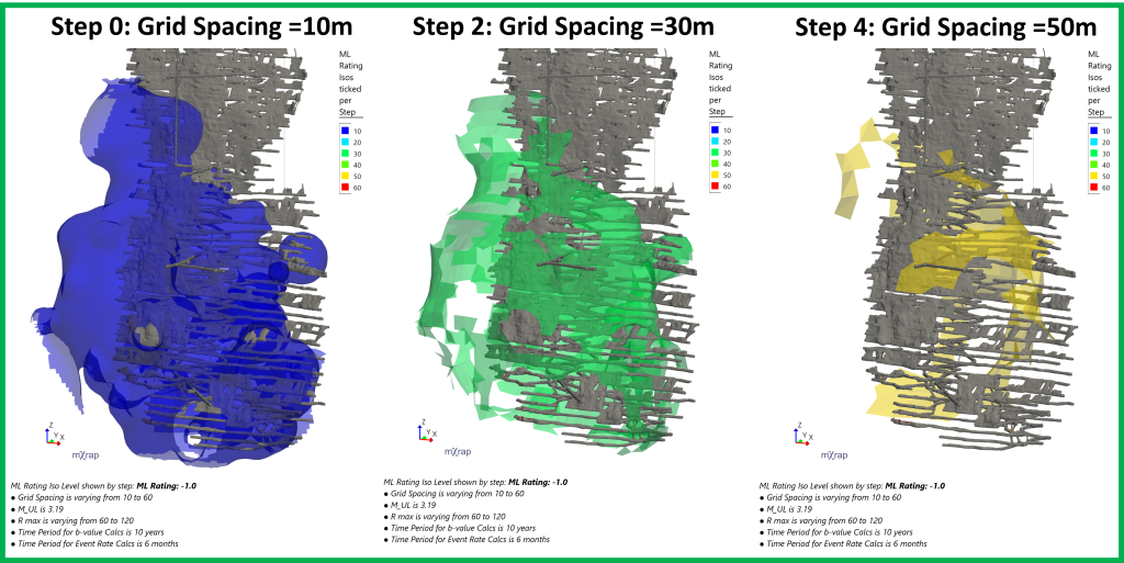
The ML Rating is the design magnitude that would have a probability of exceedance of 15%. The ML Rating Isossurface can be visualised in the 3D view for each ML Rating Level ticked for each step (Figure 4).
Hazard on excavations
The Excavation View estimates the seismic hazard associated with working areas (minode locations) in a few different ways. More details can be found on blog post : https://mxrap.com/2019/01/12/hazard-assessment-app-excavation-view/
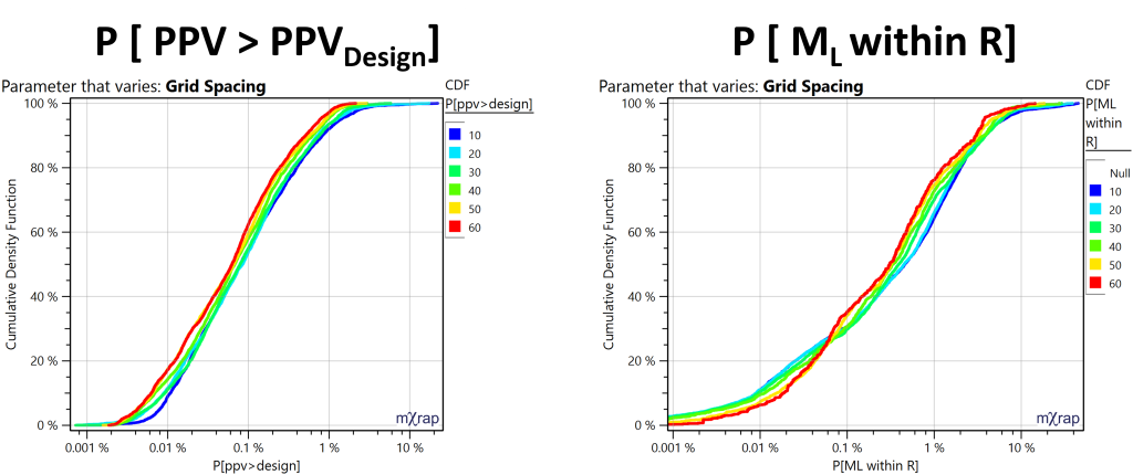
The effect of the input parameters variations can be visualised on the hazard on excavation, expressed by the P [ML within R] and P [PPV > PPVDESIGN]. The distribution of both parameters for each minode can be seen for each step (Figure 5).
