The strong ground motion (SGM) relationship is used to calculate the peak particle velocity (PPV) generated by a seismic event. You may also hear this referred to as a ground motion prediction equation (GMPE), but only the maximum velocity is estimated, i.e. the strong ground motion, rather than the full, complex wave motion.
The PPV is generally calculated for a specific location based on:
• distance to the seismic event (R)
• source magnitude (ML)
• source radius (Rs)
• static stress drop (SSD)
The source radius can be computed as a function of magnitude and the adjustment due to SSD is sometimes excluded. So PPV is often simply a function of ML and R.
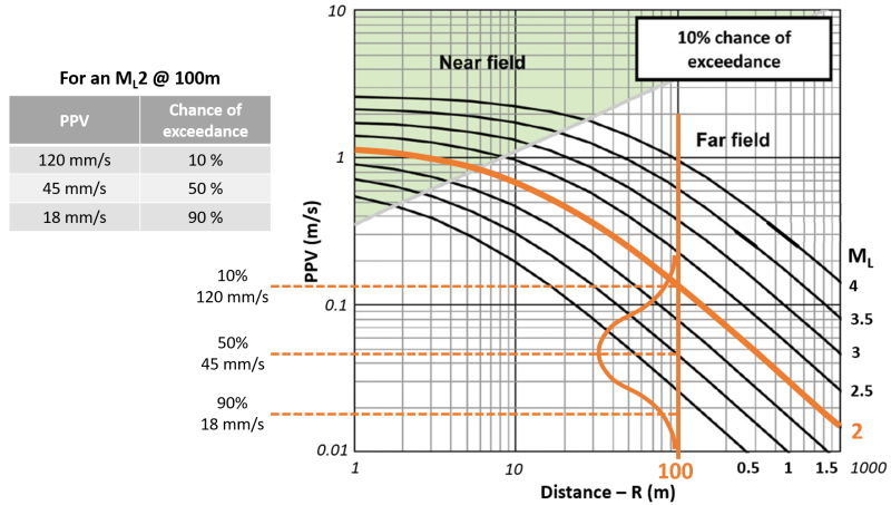
You have probably seen the SGM relationship illustrated in a similar way to the figure below. What is sometimes not recognised is there is an associated uncertainty in these relationships. In the case below, the PPV values are based on a 10% chance of exceedance for a given ML and R.
The wave motion from a seismic event through the rock mass is highly complex and uncertain. So, for a given ML and R, the PPV is not a single value but a probability distribution. This is illustrated below, for a ML2 at a distance of 100 m, the PPV distribution is plotted along with the 10th, 50th and 90th percentile values for probability of exceedance.
There are many factors that contribute to the uncertainty in ground motion that results from a seismic event. The ground motion does not radiate from a seismic event uniformly. Each source mechanism has its own radiation pattern where the magnitude of the ground motion varies depending on the direction. The radiation pattern also differs for the P-wave and S-wave.
As the body waves radiate outwards from the source they attenuate but rock mass anisotropy affects the rate of attenuation. The wave attenuates faster when cutting through lamination than it does when travelling along (parallel) to the bedding or foliation plane.
Excavations, different lithologies and major contacts and discontinuities will create reflections and refractions. The wave will split into a separate P-wave and S-wave when it reflects off a boundary or refracts into a new medium. Multiple waves can superimpose to create stronger ground motions that the individual waves.
Surface effects
The SGM relationship does not give the PPV expected on the excavation surface. The SGM equation is based on the recorded PPV at sensors which are normally installed well into the rock mass, away from the excavation surface. So, the calculated PPV includes the uncertainty from different radiation patterns, natural variability, reflections and refractions but does not include surface effects. The strong ground motion of the body wave, without including the effect of the excavation surface, is sometimes referred to as PPV’. The true surface PPV is the PPV’ with an additional amplification factor applied.
The amplification is due to a couple of different effects of the surface. The amplitude is expected to double at the free surface due to the superimposition of the incoming wave and the reflected wave. The amplification is more than double for a corner pillar due to the closed geometry. The body waves can also interact with the free surface to form Rayleigh and Love surface waves. These waves propagate along the surface rather than through the rock mass. The low velocity fractured zone around the excavation can enhance the formation of surface waves as the seismic energy is trapped between the free surface and the fracturing boundary. Waves also increase in amplitude as they move into a lower velocity medium such as the fractured zone.
In earthquakes, surface waves cause the most damage to infrastructure. The amplitude of Rayleigh and Love waves tend to be higher than body waves. Surface waves also attenuate more slowly, i.e. travel further, since the geometric attenuation is only along the surface rather than all three dimensions. Another common observation with earthquake damage is that buildings on soft soils are more heavily damaged than buildings on solid rock. This is a similar case as the fractured zone around excavations although there is less experimental evidence of this phenomenon in underground tunnels.
If you are interested in reading more, these papers are a good place to start:
• Potvin and Wesseloo (2013) – Includes a discussion of factors influencing dynamic demand on ground support.
• Wesseloo (2018) – Description of the SGM relationship and hazard calculations done in mXrap.
Procedure for site specific SGM calibration
The SGM relationship is used to calculate PPV in the Hazard Assessment and Large Event Analysis apps. The default relationship is from the Canadian Rockburst Support Handbook. This relationship is mostly based on recorded ground motions at Brunswick, El Teniente and Creighton mines and may not be applicable to your site. It is fairly simple to calibrate your own site specific SGM relationship using the data recorded by your seismic system. The PPV is recorded by each sensor for each event. With this data, we have a tool to calibrate your site specific SGM relationship. If you would like to do this for your site, the procedure is as follows:
1. Export your PPV data from your seismic database. We have done this a few times for IMS data. It is called an Event-Trigger query that is a table with a row for each sensor hit per event. Contact our support email address if you need assistance. We need the export to include the sensor location, sensor PPV, event date, event time epoch seconds, event location, site id, site location, geophone frequency, sensor type and #trigger accepted.
2. Save the PPV data into the #Data folder in your root and run a default backup in mXsync. Contact our support email address to let us know you would like us to calibrate your SGM relationship.
3. We will generate your site specific SGM equation and send the info back as a patch in mXsync.
4. Apply the patch in mXsync and run another default backup.